Start of topic | Skip to actions
Shock-induced vibrations of a beam-like panel
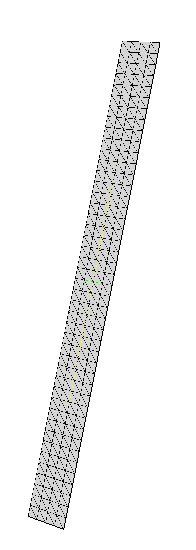
This example is intended as a verification test for AMROC-SFC. It repeats the calculation of Shock-induced Beam Vibrations in with SFC. The computation is carried out in 3D, but panel and fluid domain are very shallow to ensure beam-like structural behavior.- SFC mesh of thin panel: 352 elements

Numerical simulations
- Three-dimensional Euler equations, shock wave of M=1.21 in air at rest (
 , 100kPa, 293K)
- Hybrid Roe-HLL Riemann solver, MUSCL reconstruction with Minmod limiter, dimensional splitting
- Source code: [fluid codes] [solid codes]
Fluid-structure interaction verification
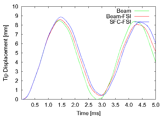
- Apply instantaneous, constant pressure difference of 100kPa along entire beam, no dynamic fluid interaction (Beam)
- Compare tip displacement with FSI simulations for beam solver and plate strip in SFC with initial condition of 100kPa pressure difference
Fluid-structure interaction results with fully dynamic impact
- Fluid domain: 0.4m x 0.08m x 0.005m, AMR base mesh 320x64x2 cells, 2 additional levels with refinement factors 2, 2. Forward facing step geometry with step of 0.015m height and 0.265m length. Reflective boundaries everywhere except left boundary (inflow).
- 322h CPU on 8 nodes with Intel 3.4GHz Xeon dual processors connected with Gigabit Ethernet (7 fluid nodes + 1 solid node), 4500 coupled time steps, expense for level set evaluation 0.74% of overall run-time
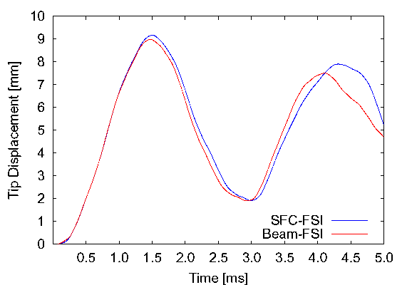
- Comparison of tip displacement with beam solver and SFC plate strip for beam of 50mm length
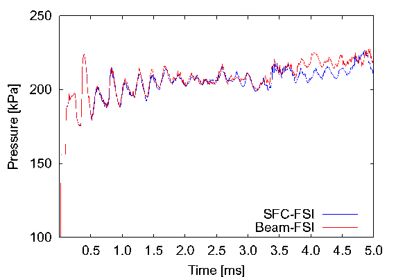
- Tracks of fluid pressure 0.01m before beam at upper boundary. Pressure difference is roughly 100kPa. Beam length 50mm.